Figure 14.1.1
It is required to design a fifth-order Butterworth low-pass filter with a de gain of unity, a passband edge of , and a maximum deviation in the passband transmission of (i.e., ).
(a) Find the transfer function and give and of each of the two pairs of complex-conjugate poles. Also, specify the frequency of the real pole.
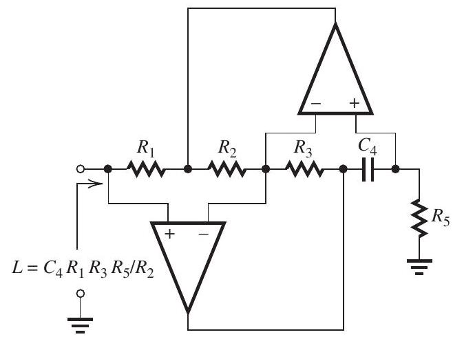
(b) Provide a complete circuit realization of the filter as a cascade of two second-order sections and a first-order section. For the second-order sections, use realizations based on the inductancesimulation circuit of Fig. 14.1.1. For the first-order section, use an op amp-RC circuit. Design so that all capacitors are equal to and as many of the resistors as possible are equal. Give the complete circuit and specify the values of all resistors.
(c) What is the attenuation achieved at the stopband edge, ?
Correct Answer:
Verified
Figure 14.1.2
Figure 14.1.2 show...
View Answer
Unlock this answer now
Get Access to more Verified Answers free of charge

